the important wires for the DPDT mod are the ones that are soldered to the old SPDT switch you will be removing.
Green - signal from pedal input jack on PC board
Blue - effected signal leaving wah circuitry, heading to switch
Purple - signal from switch to output jack on PC board
there are other wires, running to the wah pot and the battery
clip, but they don't involve the switching.
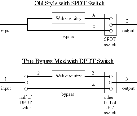
in my crude home page diagram, there are numbers next to some of the wires and connections. here are those numbers, with the colors of the wires that will make those connections.
1 - from input jack to DPDT		Green
2 - from DPDT to wah ciruitry
3 - wah circuitry to DPDT [output]	Blue
4 - bypass jumper
5 - from DPDT to output jack		Purple
connections 1,3, and 5 are simple, but 2 and 4 you have to make yourself. 4 is easy, just solder a wire across two end poles of the DPDT switch. when the pedal is bypassed, the signal will go from the input, through this wire, to the output, and not through any of the wah circuitry.
connection 2 is the tricky one.
the input signal runs from the pedal input jack onto a trace on the PC board and then up to the mounting plug where all the wires come off the board. the fork in the input signal is at this group of wires - one path for the signal is the Green wire carrying the input signal to the SPDT switch, and the other path of the fork is a trace on the PCB carrying the same signal past the plug of wires into the wah circuitry.
using a voltmeter to check connectivity between the PC board trace and the green wire, i found which trace was carrying the input signal away from the wires and into the wah guts. very carefully, i used a knife to scratch away some of the copper and break this trace, creating two dead ends.
one dead end, the "upstream" one, is connected to the green wire, and you can leave it alone. the second dead end, the "downsteam" one, is the entrance to the wah circuitry. i soldered a long wire directly onto this trace on the PCB board. the other end of this wire is soldered to the DPDT switch, so i ran the wire under the PCB up into the top of the pedal casing. this wire is connection 2.
General Notes:
i _strongly_ recommend that you use a voltmeter to check all connections - make certain which color wires are the input, output, etc. check the SPDT and DPDT switches to make sure that you know which poles of the switch are connected to each other when you stomp it on and off. also, makes notes of all the connections and all the connections you plan to make - draw a diagram just to check and make sure everything is right.
back to Equipment Page.