 Sig
Kadet Senior ARF Construction and Review
Sig
Kadet Senior ARF Construction and Review
Part 1
By
Rob Buhrman
 Until
now, I have never bought an ARF. I’ve
always built from kits to get the true satisfaction of
the sport. But I was so
impressed with the SIG Kadet LT-40 kit that my 15 year old son built, that I
started looking at the SIG line, and especially the Kadet Senior.
I had seen pictures of Seniors and was a bit turned off by its 3-channel setup, big dihedral, and spindly landing gear.
But I was really impressed with the Senior’s large wing area and light
weight.
Until
now, I have never bought an ARF. I’ve
always built from kits to get the true satisfaction of
the sport. But I was so
impressed with the SIG Kadet LT-40 kit that my 15 year old son built, that I
started looking at the SIG line, and especially the Kadet Senior.
I had seen pictures of Seniors and was a bit turned off by its 3-channel setup, big dihedral, and spindly landing gear.
But I was really impressed with the Senior’s large wing area and light
weight.
I
feel that any big plane with an engine should have ailerons.
Fortunately for me, SIG thinks the same way, and builds their Senior ARF
with nice big barn-door ailerons and very little dihedral.
They’ve already fixed two of my three objections, and I’ve got an
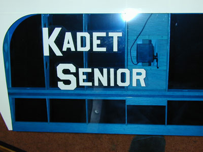
idea for fixing the third one, so I ordered a Kadet Senior ARF in transparent
blue and white.
If
you think Almost Ready to Fly means just that, think again.
To properly prepare an R/C aircraft for service, there is almost as much
work to do after the plane
is built and covered, as there is up to that point.
First, you should take the time to think about what you want to end up
with, and consider and plan any modifications you might want to do.
Parts need to be ordered and installed to do your mods.
You need to properly install the radio system, servos, pushrods, control
surfaces, hinging, engine and fuel system, cowl, and landing gear.
The engine needs to be broken in, installed, and adjusted for reliable
idle, mixture, and throttle control. Then
the aircraft must be properly balanced, and
all controls adjusted and tested before the plane is actually “Ready to
Fly”. Of course, the last
requirement for successful flight of your ARF is a competent r/c pilot.
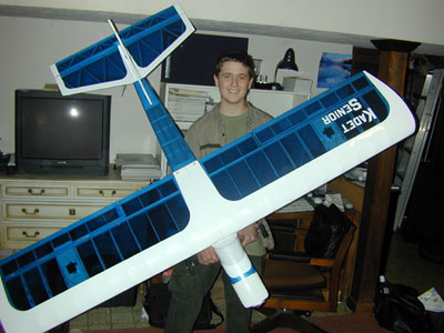
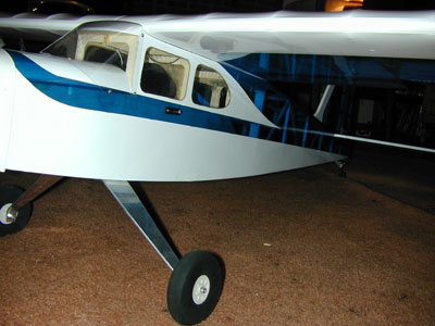
 An
ARF is really better described as a pre-built, pre-covered airframe with some
hardware, and the SIG Kadet Senior ARF is a beauty.
An
ARF is really better described as a pre-built, pre-covered airframe with some
hardware, and the SIG Kadet Senior ARF is a beauty.
The
plane came nicely packed and in just about perfect shape.
The covering just needed a bit of ironing and heat shrinking due to the
change in humidity. The wing panels
were nice and flat but the ailerons were just a bit warped, which was easily
corrected with a little reverse-twisting and the heat gun.
The fuse and tail feathers were perfectly straight and true, with just
the right amount of covering removed for the assembly points. The building and covering job is first rate, and far better
than I could ever do myself. (I’m
an average kit-builder) SIG ships the Senior ARF with a two-piece wing, for
obvious reasons, and the joint and fit is excellent.
I followed SIG’s advice and glued the metal joiners into one wing panel
so I can’t lose them. The wing
bolts on with two nylon bolts supplied.
Along
with the quality of construction, I was impressed with the very light weight of
this large structure. The covered
airframe weighs in at a mere 63 ounces. With
everything installed except the engine and engine mount, it comes in at just
under 5 ¾ lbs. With a TT Pro
.61 up front on Du Bro iso mounts totaling 32 ozs., this big bird’s total dry
weight ready-to-fly is 7 ¾ lbs. The
80 inch wing has 1180 square inches of area, so it works out to about 15 oz/sq.
ft. of wing loading. A very nice
number for pilot training and leisurely flying.
By
the way, SIG recommends a .40 - .46 size engine to power this plane, and I’m
sure that is plenty, but I know it needs about 32 oz on the front end to
balance, and I just hate adding lead. Besides,
a .40 looks so tiny on that big firewall! I’m
sure there are limits on the size engine that this airframe can handle, but
I’m not building this plane to race, and the iso mounts reduce vibration quite
a bit. I expect a lot of my flying
with the Senior to be at ¼ throttle. Just
the same, I spread a little epoxy around the firewall-to-fuse joint for good
measure.
 The
first task was hinging. Whatever
you do in building a plane, make SURE your hinging is good and strong. The CA
hinges supplied in the kit are fine, but I didn’t do well with the gluing
method in the instruction manual. SIG
instructs you to attach the all parts dry and then flex them and apply CA glue,
which is supposed to “wick” down into the hinge/wood joint.
Well I’m sure it can be done, but I wasn’t having much luck getting a
super strong hinge joint, so here’s what I did:
The
first task was hinging. Whatever
you do in building a plane, make SURE your hinging is good and strong. The CA
hinges supplied in the kit are fine, but I didn’t do well with the gluing
method in the instruction manual. SIG
instructs you to attach the all parts dry and then flex them and apply CA glue,
which is supposed to “wick” down into the hinge/wood joint.
Well I’m sure it can be done, but I wasn’t having much luck getting a
super strong hinge joint, so here’s what I did:
1)
Spread CA on both sides of one half of the hinge and slide it into the
control surface. Solidly glue all
the hinges into the control surface this way and allow to dry for a few minutes.
2)
With no glue, fit the control surface onto its mating structure and
adjust until it is perfectly aligned.
3)
Get some round toothpicks, cut them in half, and find a drill bit that
will make a “snug” hole for one. Drill
two holes through the mating structure that go through each hinge.
If possible, stop just short of coming out the other side.
If you go all the way through, that’s ok.
Just be certain you’ve gone through the hinge.
With a light drill, you should be able to feel it.
4)
Using CA, plug the holes with the cut toothpicks.
Allow to dry, then saw off the protruding (sharp) ends, and sand flush.
I
used this method drilling from the bottom of the wing and horizontal stab so you
can’t even see anything on top. If
you want you can cut little pieces of covering and iron over the toothpick ends
to perfect the job. This method
results in a hinge joint that I feel is more than strong enough for my purposes,
and allows me to really align the parts properly.
Next
I did the aileron servos installation. This
is pretty straightforward, but don’t rush it.
First of all, whenever I’m doing anything with a servo, I like to hook
up the radio system, put all the trims at neutral, and let the servo take it’s
neutral position. I also check the
direction of travel and reverse it on the transmitter if necessary before
anything is installed. That way
when I install servos and control arms and horns, everything is very close to
where it should be. Just be very
careful not to aggravate the wiring and connectors in the servos, receiver, and
battery pack. Your airplane’s
life depends on these connections being solid for a very long time.
 The
Senior uses a servo for each aileron. I
spent some time thinking about left and right and marking them, but then
realized it doesn’t matter…because each servo gets the exact same signal
(from a Y-connector off the receiver) and each servo moves in exactly the same
way. But because the servos are
oriented opposite to each other, the ailerons work like they’re supposed to.
By the way, I installed a simple 4-channel Futaba 4VF radio system with 5
3004 servos.
The
Senior uses a servo for each aileron. I
spent some time thinking about left and right and marking them, but then
realized it doesn’t matter…because each servo gets the exact same signal
(from a Y-connector off the receiver) and each servo moves in exactly the same
way. But because the servos are
oriented opposite to each other, the ailerons work like they’re supposed to.
By the way, I installed a simple 4-channel Futaba 4VF radio system with 5
3004 servos.
I
was very careful to get the placement of the servo and control arm nicely
centered so as to avoid any binding later.
Once I got the servo where I wanted it on the plastic cover, I lightly
CA’d it in place first, then installed the hardwood mounting blocks.
This made it much easier to put the assembly together.
The hardwood mounting blocks are epoxied and screwed in place.
Although the wing panel was precut and reinforced for the servo, I had to
enlarge the opening to allow free movement. Again, it’s helpful to have the
radio activated for testing even as you’re fitting things together, as this
binding didn’t show up except when the servo was actuated, with the servo arm
and pushrod installed. When
screwing the whole thing onto the wing panel, I used a bit of CA to strengthen
the joint.
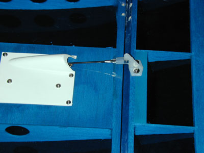
All
that was left was the installation of the aileron control horns.
A tip about installing these: Don’t
mark and pilot drill both holes at once. The
horn usually will come out crooked. Mark,
drill, and screw one side in, then square up the horn and do the second hole.
I attached the clevis to the lowest hole in the horn, as I like to have
plenty of throw on my control surfaces. As
on all clevises, I put on a ¼” piece of fuel tubing to secure it.
A
nice touch is to get a couple of 5/16” rubber grommets for the aileron servo
wire exit holes, which are at the wing center joint.
That’s it for the wing.
 Next
step was landing gear. I love
conventional gear (taildraggers) and always build my planes that way if
possible. One reason is that the
nose gear is a pain, especially on bumpy fields (which I usually fly from).
A nose gear with a problem can cause a really ugly landing. Secondly, I like the ground handling better on a taildragger.
Third, a conventional gear is all ready positioned properly for attaching
floats if you want to fly off water. But most of all, the type of planes I like just look better and take off
and land better with that configuration. I
really don’t know exactly why. (My
son agrees and thinks those little wire gear that come standard on these planes
look silly)
Next
step was landing gear. I love
conventional gear (taildraggers) and always build my planes that way if
possible. One reason is that the
nose gear is a pain, especially on bumpy fields (which I usually fly from).
A nose gear with a problem can cause a really ugly landing. Secondly, I like the ground handling better on a taildragger.
Third, a conventional gear is all ready positioned properly for attaching
floats if you want to fly off water. But most of all, the type of planes I like just look better and take off
and land better with that configuration. I
really don’t know exactly why. (My
son agrees and thinks those little wire gear that come standard on these planes
look silly)
I
started by epoxying a bit of hardwood on the fuse tail floor to screw the Great
Planes scale tailwheel assembly into. That
was easy. I used a Great Planes 2-56 pull-pull system hooked up to the
rudder servo to control the tailgear. I
felt it was the simplest way to do it on this plane.
 For
the main gear, I knew it would be placed right around the leading edge of the
wing, but there aren’t any hard and fast rules about placement, so I pieced
the whole plane together and played around with the position of the aluminum
Dural landing gear until it looked and felt like it was correct.
The center of the landing gear ended up being 8 ¼” back from the
firewall, which puts the axle just about 1/8” behind the wing leading edge.
I just epoxied a hardwood block on the fuse floor, on either side of the
front former, then drilled three holes in the gear plate and screwed in three #8
screws with a little CA to harden the threads in the wood.
Once I knew where I wanted the gear to go, I used a square to mark a line
exactly perpendicular to the fuse length and made sure the gear plate lined up
perfectly. I used the nice 3 ½”
lite foam wheels that came with the kit, drilled out just a touch to slide onto
the 8-32 socket head screws that serve as axles.
Finally, I CA’d a balsa strip into the old landing gear groove and
covered with a little patch of white Monocote.
For
the main gear, I knew it would be placed right around the leading edge of the
wing, but there aren’t any hard and fast rules about placement, so I pieced
the whole plane together and played around with the position of the aluminum
Dural landing gear until it looked and felt like it was correct.
The center of the landing gear ended up being 8 ¼” back from the
firewall, which puts the axle just about 1/8” behind the wing leading edge.
I just epoxied a hardwood block on the fuse floor, on either side of the
front former, then drilled three holes in the gear plate and screwed in three #8
screws with a little CA to harden the threads in the wood.
Once I knew where I wanted the gear to go, I used a square to mark a line
exactly perpendicular to the fuse length and made sure the gear plate lined up
perfectly. I used the nice 3 ½”
lite foam wheels that came with the kit, drilled out just a touch to slide onto
the 8-32 socket head screws that serve as axles.
Finally, I CA’d a balsa strip into the old landing gear groove and
covered with a little patch of white Monocote.
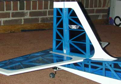
Next
came attaching the tail feathers. Since
this is a very permanent epoxy joint, I always take my time and triple check all
measurements, dry fit the pieces, and get my clamps all ready before mixing any
glue. The instructions will guide you perfectly through this step,
so, as always, follow them carefully. My
horizontal stab was a breeze to line up and attach, as it sat perfectly square
on the saddle and just naturally went into the proper position.
I applied the 5-minute epoxy, lightly set the clamps in place, and
checked and adjusted the measurements from wing saddle to stab tips before
putting final pressure on the joint. Once
dry, (I like to give it about an hour or so) the vertical fin can be epoxied
into place. I used two square pieces of wood, set on the horizontal stab,
to “sandwich” the fin and be sure it sits perpendicular to the stab.
Once the epoxy was applied, I ran some masking tape from top of the fin
to the end of the horizontal stab on either side to act as a clamp to hold the
joint stable, and allowed it to dry for an hour or so.
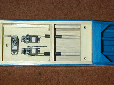 Since
SIG did such a nice job installing the plywood servo tray, I decided to use it.
First, I ran a little bead of epoxy around the joint just for a little
extra security. Then I installed
the servos according to the instructions.
I added a drop of CA on each servo hold-down screw for good measure.
Since
SIG did such a nice job installing the plywood servo tray, I decided to use it.
First, I ran a little bead of epoxy around the joint just for a little
extra security. Then I installed
the servos according to the instructions.
I added a drop of CA on each servo hold-down screw for good measure.
The
pushrods go together very nicely. Be
sure to create a good, solid epoxy joint between the metal rods and the balsa
pushrods. Use a heat gun to shrink
the supplied tubing over the joint for a nice finish.
I like the fact that the rudder pushrod needs no bending or curving, but
is a perfectly straight run from servo to rudder control horn.
The elevator pushrod is, of course, also a straight run.
To
eliminate any possible slop in the control, drill out just enough of the servo
arm hole to give you a nice, snug fit with the Z-bend rod.
Attach the Z-bend rod through the top of the servo arm with the arm
removed, then fit the arm onto the servo. The
measurements for the pushrods in the plans are perfect, and will give you just
the right amount to work with at the clevis end.
After
bolting on the rudder and elevator control horns according to the instructions,
I attached the clevises to the innermost holes in the horns, for maximum throw. When measuring the throws, they came out just a bit longer
than the instructions recommend. Perfect
for me. Don’t forget the fuel
tubing keepers.
Rather
than mounting the receiver switch in the servo mounting tray, I used a Great
Planes switch/jack mounting set and installed it on the left side of the fuse
just below the left front window.
The
setup and installation of the supplied fuel tank is very straightforward. To prepare, I epoxied a little latex foam to the middle of
the tank retaining block, so the back of the tank will be resting against foam
rather than wood. For installing
the fuel pickup tube and clunk, I cut about ¼” from the supplied tubing.
It is very important that the pickup tube and clunk weight are completely
free to move within the tank. Check
this by rotating the tank and watching the clunk.
If it sticks in any position, shorten the tube a bit until it’s free to
always reach the “gravity bottom”. That
way, the clunk can always get to where the fuel is even when the plane is flying
inverted. I also use a ¼” of
tubing as a “keeper” for all fuel line connections.
To get the keeper around the fuel line, place the keeper on the end of
needle nose pliers, spread the jaws, and push the fuel line through.
I
put the tank together according to the instructions, tightened the plug, then
filled the tank with fuel and tested it for leaks before installing it into the
plane.
In part two, we'll get the new Thunder Tiger .61 power plant ready, break it in and install it.
-rb