 Sig
Kadet Senior ARF Construction and Review
Sig
Kadet Senior ARF Construction and Review
Part
2
By
Rob Buhrman
In
Part 1, we prepared everything but the engine on our Kadet Senior ARF.
Now, this beautiful aircraft is ready for it’s powerplant.
I
like to think of an airplane’s engine as its’ most important safety feature.
Nothing can cause trouble on a flight quicker than a balky engine.
On the other hand, a strong, reliable, responsive engine can not only
keep the pilot out of trouble, it can also save him in some situations.
There’s nothing like instantly available thrust when you need it.
 I
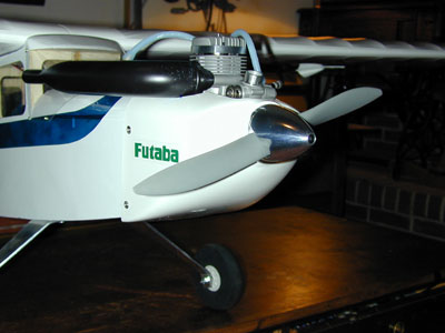
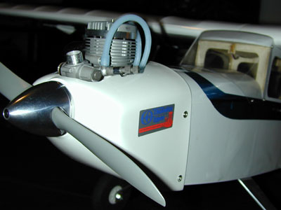
chose Thunder Tiger’s Pro .61 2-stroke engine for my Kadet Senior.
This dual ball bearing, ABN design powerplant can produce 1.8 horsepower
at 15,000 rpm.
It weighs in at a hefty 27 ounces, which perfectly balances my
tail-dragger Senior.
It should swing a big 13x6 prop at low rpm, giving me the quietness I like,
and having plenty of “juice” in reserve for some aerobatics if I choose.
I’ve been very happy with the performance of our TT .46 Pro which
we’re flying on our Kadet LT-40.
And the .61 Pro is very reasonably priced, at $99 street.
I
hate airframe vibration, so I’ve tried several vibration-reducing
engine mounts over the years.
This time, I’ve chosen DU-BRO’s .50-.75 2-cycle vibration reducing
aluminum motor mount system.
$25 is quite a bit to spend on mounts, but when I saw the quality of
these, I felt it was worth it.
I soaked the elastomeric (rubber) elements in fuel, according to the
instructions, before inserting them into the mounts. I like to tap the mounts for the engine mounting bolts, and I did so here
with a #36 drill bit and 6-32 tap.
Before doing that however, I played around with balance, and ended up
moving the engine a bit forward from the distance specified in the instructions.
I knew this might affect the pre-drilled cowl, but I was determined to
balance the aircraft without adding dead weight.
I epoxied some balsa blocks to the firewall so the cowl could be mounted
further forward, while still using the pre-drilled holes in the cowl.
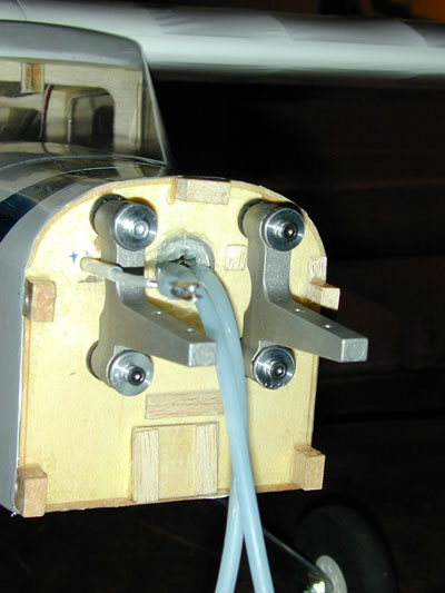 Since
these mounts are much bigger than those supplied with the Senior, I couldn’t use
the pre-drilled holes in the ARF’s firewall, or the pre-installed blind nuts.
I filled the holes with balsa and epoxied over them to fuel-proof.
I also filled (or covered with pieces of balsa) and fuel –proofed all of the pre-drilled holes in the
firewall, as they’re not needed for the nosegear and its pushrod.
Since
these mounts are much bigger than those supplied with the Senior, I couldn’t use
the pre-drilled holes in the ARF’s firewall, or the pre-installed blind nuts.
I filled the holes with balsa and epoxied over them to fuel-proof.
I also filled (or covered with pieces of balsa) and fuel –proofed all of the pre-drilled holes in the
firewall, as they’re not needed for the nosegear and its pushrod.
Now
the task was to determine where to drill holes for the new mounts.
Here’s how I did it:
1)
Tape or tack glue the engine temporarily onto the mounts
2)
Test different possible positions and see how the mounts fit on the
firewall, muffler clears fuselage, how the cowl would need to be cut out, etc.
3)
After deciding on engine orientation (in this case upright) take it away
and fit the cowl onto the fuse.
4)
Take a long piece of piano wire, maybe 3 feet, and attach with tape to
the top of the fuse.
Bend in a curve so that the end of the wire points just in front, and
exactly centered, in the round front opening of the cowl.
Be sure this positioning is correct during the next step.
5)
Hold the engine and mount in place so that the end of the prop shaft
lines up perfectly with the wire, and mark the centers of the mount’s holes on
the firewall.
Now
that the position is marked, I just drilled the holes and installed the blind
nuts. A
little tape wrapped around the finger (to stick the blind nuts onto) made it
possible to feed them in through the fuel tank opening and hold them in place
for installation.
This is a bit tricky, so rather than try to hold the mount in place
before the blind nut was set, I threaded a nut onto one of the mounting bolts to
set the nut into the back of the firewall permanently.
Now
the mounts are drilled and tapped for the 6-32 mounting screws I chose.
I used a nail and tapped lightly with a hammer to mark the drilling
spots, which need to be drilled very precisely.
Don’t forget to take it slow, back the tap out
and use plenty of oil when tapping threads.
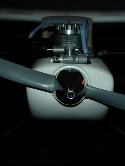
I
attached the mounts and engine to the firewall and began the process of
measuring, marking and creating the opening in the cowl.
A Dremel tool and sanding drum work well.
After creating the initial hole, I took a little at a time, constantly
going back to re-fit, measure and mark where I needed to remove more.
Finally,
I was happy with the cut-out in the top of the cowl, and found that the position
of the prop shaft and thrust washer was a little skewed to the left.
I added a couple of washers between the left mount and firewall as shims,
which made the fit perfect.
Now time for engine break-in and bench test.
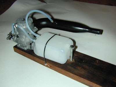
 I’ve
always used homemade engine test stands, which consist of a cut out piece of
5/8” thick
hardwood – walnut in this case.
When marking and sawing the opening for the engine, I’m very careful to
make it just large enough for the crankcase to fit, so that there’ll be enough
wood around the mounting holes once they’re drilled.
I use the ¼” lag bolt to actually screw the mount into the wood work
surface in my shed.
This is a super solid way of attaching the test stand, but I don’t
recommend it if you like your worktable.
I’ve
always used homemade engine test stands, which consist of a cut out piece of
5/8” thick
hardwood – walnut in this case.
When marking and sawing the opening for the engine, I’m very careful to
make it just large enough for the crankcase to fit, so that there’ll be enough
wood around the mounting holes once they’re drilled.
I use the ¼” lag bolt to actually screw the mount into the wood work
surface in my shed.
This is a super solid way of attaching the test stand, but I don’t
recommend it if you like your worktable.
 I
always have two problems when starting a new engine for the first time…not
enough fuel, and too much fuel.
After several attempts and priming, I removed the glow plug, turned the
whole thing upside down, and cranked the engine to remove all the fuel.
Then the engine started up.
By the way, I used the recommended 11x6 prop for break-in.
I ran the first tank with the needle valve set quite rich, and then
leaned it out a bit for the second tank.
The idle-adjust screw needed a bit of leaning out too, about 1/8 turn.
By the middle of the second tank, the engine was running beautifully,
with immediate response to changes in throttle, and good idle.
Thunder Tiger says that the rest of the break-in can be done on the
airplane. I
felt that this engine was ready, so after running the second tank of fuel, I cranked a few drops of after-run oil into
the engine and re-mounted it on the plane, still with the 11x6 break-in prop attached.
I
always have two problems when starting a new engine for the first time…not
enough fuel, and too much fuel.
After several attempts and priming, I removed the glow plug, turned the
whole thing upside down, and cranked the engine to remove all the fuel.
Then the engine started up.
By the way, I used the recommended 11x6 prop for break-in.
I ran the first tank with the needle valve set quite rich, and then
leaned it out a bit for the second tank.
The idle-adjust screw needed a bit of leaning out too, about 1/8 turn.
By the middle of the second tank, the engine was running beautifully,
with immediate response to changes in throttle, and good idle.
Thunder Tiger says that the rest of the break-in can be done on the
airplane. I
felt that this engine was ready, so after running the second tank of fuel, I cranked a few drops of after-run oil into
the engine and re-mounted it on the plane, still with the 11x6 break-in prop attached.
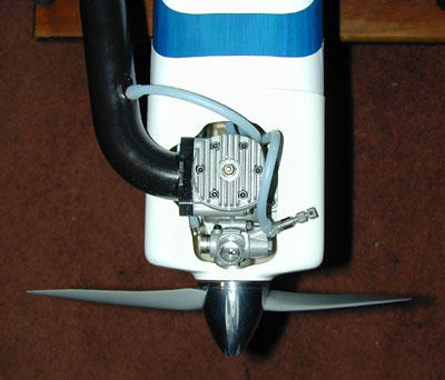 By
the way, I was not able to figure out how to slip the cowl over the mounted
engine, so the two go on together.
I used a little LockTite on the mounting screws and muffler mounting
bolts.
By
the way, I was not able to figure out how to slip the cowl over the mounted
engine, so the two go on together.
I used a little LockTite on the mounting screws and muffler mounting
bolts.
The muffler, by the way, is a Macs. I like the streamlined look as opposed to the stock muffler. It's also very lightweight. The combination of this muffler and the vibration isolating mounts makes for relatively quiet operation. The spinner is a Great Planes 2" aluminum. This is so much easier to install than the plastic ones, I'll never go back. I did need the prop adapter nut (purchased separately) but it's worth it. You can mount the prop just how you want it and don't have to worry about the backplate moving. And aluminum doesn't turn to dust when the starter cone rubs it. Last but not least, it looks really good!
All
systems go. This plane is ready for the air. In the next part, we'll
take her to the field, do the pre-flight check out, and if everything's solid,
take her up.